A 2026 Top CNC Horizontal Lathe Buying Guide should help buyers match machine capability to real production needs, not just compare impressive specifications. A Cnc Horizontal Lathe can turn shafts, sleeves, and other rotational parts efficiently, but the right model depends on the workpiece, required tolerances, and expected production volume. A long shaft may need a larger turning length and steady support, while repeated chucking work may benefit more from a reliable bar feeder and quick tool changes.
Start with the largest part you actually plan to machine. Check swing, turning diameter, distance between centers, chuck size, and spindle bore against your drawings. Then consider spindle speed and torque, turret capacity, control-system familiarity, and chip removal. These details affect cycle time and daily usability. A machine that fits the part but struggles with the material is not a good fit. Not glamorous, but important.
Installation and ownership costs also deserve attention. Confirm floor space, power requirements, foundation needs, tooling, training, warranty terms, and local service access with the supplier. Ask for a sample cut or a cycle-time estimate using your material and operation sequence; a brochure cannot prove production performance. I would be cautious about choosing the largest or fastest machine by default. Extra capacity can be useful, yet it can also mean higher purchase and operating costs. No checklist removes every uncertainty. Use this guide to compare practical options, identify trade-offs, and ask sharper questions before investing.
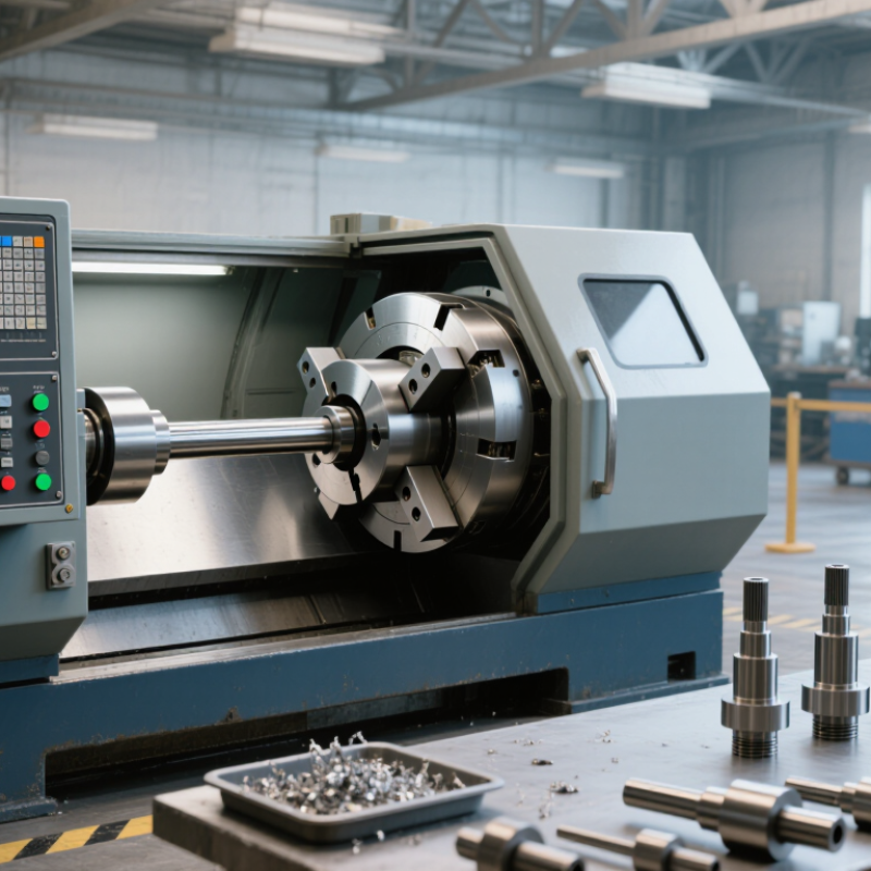
A CNC horizontal lathe holds a workpiece in a horizontal spindle and rotates it against cutting tools. This layout suits shafts, bushings, and other round parts. Gravity helps chips fall away from the cutting zone, though long chips can still collect around the chuck. A small detail, but worth checking during a machine demonstration.
The basic configuration is often a two-axis machine, using X and Z motion for facing, turning, and boring. A turret carries several tools, so operators can complete multiple cuts without changing setups. For parts that need milled flats or cross-holes, live tooling and a C-axis add rotating tools and spindle positioning. That capability can reduce handling, but it also adds setup and programming demands. More axes are not automatically better.
Production needs may point toward a different arrangement. A subspindle can grip and finish the back of a part after the main spindle completes its work. Twin-spindle machines can support higher throughput, but only when part flow and tooling are planned carefully. Bar-feeding configurations suit repeated production from stock, while chucking setups handle individual blanks or castings. Compare the machine’s working envelope with actual part drawings, including jaw clearance and bar diameter. I would not choose from spindle speed alone; the right configuration depends on material, tolerances, batch size, and operator skill. One overlooked constraint can change the whole calculation.
Start with the parts, not the machine’s headline specifications. List each workpiece’s maximum diameter, length, material, and finished tolerances. A steel shaft measuring 800 millimeters long needs different support than a short aluminum sleeve. Note whether parts require deep bores, multiple shoulders, or repeated face cuts. These details affect swing, center distance, tooling access, and whether a tailstock or steady rest is useful. Small oversights here can narrow your options later.
Production volume matters just as much. A few custom shafts per week may favor flexible setup and straightforward changeovers. Repeated batches place greater value on tool capacity, reliable cycle times, and quick loading. Consider how blanks reach the spindle and where finished parts go. If an operator must lift heavy stock by hand, the workflow deserves attention before purchase. I’ve seen capacity numbers look impressive on paper while the actual work envelope felt cramped. It is worth checking a real part drawing against the machine layout.
Tips: Bring sample drawings and a typical production schedule to the supplier. Ask for a cut demonstration using similar material, then check chip flow, access for measurement, and setup time. Keep one awkward part in the review; it may reveal a limitation your standard parts hide.
A horizontal lathe should be matched to the parts you actually make, not just the largest part listed in its specifications. Compare swing over bed, turning diameter, distance between centers, and spindle bore. A generous bore matters when bar stock feeds through the spindle. Check chuck size and spindle torque, too; high power alone may not support steady cuts at low speeds in tough materials. Look for the full torque curve. It tells more than a peak figure.
Controls affect setup time and daily consistency. Check how clearly the machine handles tool offsets, alarms, work coordinates, and program verification. Can operators preview a toolpath and recover from an interrupted cycle without guesswork? Small details matter. A cramped screen or confusing alarm can slow a shift. Automation options should fit the production mix: a bar feeder suits repeated bar work, while a parts catcher or robot may help with varied batches. Compare loading time, changeover effort, and guarding requirements alongside cycle time. A spreadsheet comparison is useful, but imperfect; test a representative part, measure chip flow, and watch an operator set up the job.
Machine quality is best judged through evidence, not polished brochures. Review spindle runout, axis repeatability, and vibration during a representative cutting test. Ask for measured results. A test part should show consistent dimensions and a clean surface finish. Check how the machine behaves after warming up; thermal drift can affect accuracy during longer production runs. A spotless showroom can mislead. I would still request time to inspect the machine under realistic operating conditions.
Service matters when a machine stops, not only during installation. Ask how quickly technicians typically respond, which spare parts are stocked, and what training is included. Get the details in writing. Confirm that operators can access routine maintenance points without awkward reaches or special tools. Safety features deserve the same close review: inspect enclosure doors, interlocks, emergency stops, and chip handling. Test them with qualified staff present. Small oversights can become daily frustrations.
Compare total cost, not just the purchase price. Include installation, foundation work, tooling, coolant systems, energy use, maintenance, and operator training. Estimate the cost of downtime, too. A lower-priced lathe may need more setup or service; a higher-priced one may not pay back as expected. Numbers can be imperfect, so record your assumptions and revisit them with production staff. Their practical feedback often changes the estimate.
Choosing a CNC horizontal lathe in 2026 starts with the parts, not the machine brochure. Record maximum diameter, swing, turning length, material, and the tightest tolerance. A long, slender shaft may need steadier support than its weight suggests. Check spindle speed and torque across your actual cutting range; peak figures can mislead. Ask for a demonstration using a comparable workpiece, tooling, and cut. Watch chip flow, coolant reach, and access to the chuck.
Tips: Bring a drawing, tolerance notes, and a list of recurring jobs. Measure twice. During acceptance, verify positioning and repeatability with a documented test, then inspect a finished part. Run it warm.
Before purchase, confirm floor loading, power, coolant handling, and service clearance. Review tool capacity, programming support, and any bar-feeder needs with the people who will use the machine daily. Request written specifications and clarify what the acceptance test covers. A showroom cycle is useful, but it cannot reveal every production issue. Leave some room for future work without paying for capacity that may sit idle. Real chips rarely behave as neatly as they do in demonstrations.
Use this checklist to compare machine specifications against the actual part, material, workholding, and production plan. Capacity figures are machine-specific; confirm them in the manufacturer’s current technical documentation and with an application test.
| Selection dimension | What to specify | Practical selection guidance | How to verify before purchase |
|---|---|---|---|
| Part envelope | Maximum workpiece diameter and overall length, in mm or inches | Compare the part with the machine’s stated maximum turning diameter and usable turning length. Allow clearance for the chuck, jaws, tools, and any required tailstock or steady rest. | Request a layout drawing showing the part, workholding, toolholder, and machine travel in the proposed setup. |
| Swing and turning clearance | Swing over bed; maximum turning diameter over the carriage or cross-slide | Swing over bed is a clearance measure, not necessarily the diameter that can be machined. Use the stated turning diameter for the intended tool and setup. | Confirm the measurement definitions in the specification sheet and check for interference across the complete toolpath. |
| Turning length and axis travel | Usable turning length; X- and Z-axis travel; tailstock or sub-spindle requirements | Do not assume distance between centers equals usable cutting length. Tooling, chuck depth, part projection, and support equipment reduce available working space. | Review the machine layout and simulate the longest part program with the intended tooling and workholding. |
| Bar capacity and spindle bore | Spindle bore, bar capacity, liner dimensions, and bar-feeder interface | The usable bar diameter depends on the spindle passage, drawtube, liner, chuck, and feeder. Check the full bar path rather than spindle bore alone. | Obtain a dimensioned bar-capacity drawing and verify the proposed bar diameter and feeder setup with the supplier. |
| Chuck and workholding | Chuck type and size, through-hole, jaw range, clamping force, and rated speed | Select workholding for the part’s size, material, and operation. Chuck speed limits and permissible clamping conditions must be observed at the intended spindle speed. | Check the chuck maker’s speed and force data, then confirm compatibility with the spindle nose and machine safety limits. |
| Spindle speed and torque | Maximum speed, continuous power, and torque-versus-speed curve | Maximum RPM alone does not indicate cutting capability. Match the torque range and continuous power to the material, cutting diameter, and planned operations. | Request the spindle power and torque curve, including duty conditions, and review it against the intended cutting data. |
| Cutting tools and turret | Turret station count, tool interface, live-tool capability, and tool size | Choose enough stations for the process while considering tool access, indexing time, and clearance. Live tooling is useful when milling or drilling features can be completed in one setup. | Confirm tooling compatibility, live-tool speed and power, station configuration, and collision clearance with the proposed part program. |
| Accuracy and repeatability | Positioning accuracy, repeatability, thermal behavior, and part tolerance requirements | Machine-axis specifications are not the same as finished-part accuracy. Results also depend on temperature, tooling, workholding, material, and cutting conditions. | Review the measurement method and test conditions. Run a representative part trial and measure the critical features with suitable calibrated equipment. |
| Chip and coolant management | Coolant delivery, filtration, chip conveyor, tank capacity, and chip type | Long, stringy chips and high-volume production may require different chip-control and conveyor arrangements than short-chip applications. | Test the planned material and cutting strategy where possible; confirm conveyor type, coolant options, and maintenance access. |
| Controls and connectivity | CNC functions, programming workflow, file transfer, data collection, and required interfaces | Check that the control supports the shop’s programming methods, operators’ training needs, and required data or network policies. | Demonstrate the required program transfer, editing, probing, and reporting workflow using representative files. |
| Installation and utilities | Footprint, machine mass, foundation requirements, electrical supply, air, and coolant services | Include service and maintenance access in the floor plan. Site requirements vary by machine configuration and local electrical and safety codes. | Use the installation manual to confirm site readiness, rigging access, utility capacity, and any foundation or anchoring requirements. |
| Support and lifecycle cost | Commissioning, training, service coverage, spare parts, maintenance, and total installed cost | Compare the complete operating package, not only the purchase price. Account for tooling, workholding, automation, installation, training, and planned maintenance. | Request a written scope of supply, service response terms, recommended spare-parts list, and itemized quotation. |
Final verification: Compare the quoted configuration with the approved part drawing, process plan, site requirements, and acceptance-test criteria before placing the order.