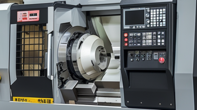
Choosing a Cnc Lathe Protective Shell is not a cosmetic decision. It affects operator safety, machine uptime, maintenance access, and production quality. A bright steel cover may look impressive, yet it can perform poorly beside coolant spray, hot chips, vibration, or repeated door movement. The right choice begins with the machine’s actual working conditions.
John Saunders, a respected CNC educator and machinist, has stated, “Safety is part of the process, not an afterthought.” That principle applies directly to protective-shell selection. A reliable shell should contain chips, resist corrosion, reduce exposure to moving parts, and support clear visibility. It should also match the lathe’s travel range, tooling arrangement, enclosure space, and cleaning routine. Small details matter. A badly positioned window can create blind spots. A weak seal can leave coolant beneath the frame.
The following seven tips examine material strength, sealing performance, heat resistance, visibility, access, installation, and long-term maintenance. Each point reflects practical workshop concerns rather than product appearance alone. No checklist is perfect. A shell that works well in a dry prototype shop may fail in a high-volume production line. That difference deserves attention. Measurements can be overlooked. Operators may also prefer easier access over stronger protection, creating an uncomfortable compromise. Reviewing these trade-offs before purchase can prevent expensive modifications later. The best Cnc Lathe Protective Shell is not simply the most durable option. It is the one that protects people and equipment while fitting the machine’s daily reality.
7 Tips for Choosing a CNC Lathe Protective Shell
Measure the machine before comparing protective shells. Record the overall length, width, and height. Then measure the chuck, tailstock, tool turret, and door travel. Leave clearance for coolant hoses and chip conveyors. A shell that fits the bed may still block maintenance access. Measure twice. Small errors become expensive quickly.
Check the spindle centerline height and the maximum workpiece diameter. Confirm the shell’s viewing panels, sliding doors, and interlocks match the machine layout. ISO 23125 identifies guarding and interlocking as key safety considerations for turning machines. The U.S. Bureau of Labor Statistics reported a 2023 manufacturing injury and illness rate of 2.7 cases per 100 full-time workers. Proper enclosure design cannot remove every hazard, but poor compatibility can increase exposure.
Request a compatibility drawing before ordering. Compare mounting points, door swing, cable routes, and emergency-stop access. Confirm the shell tolerates coolant, heat, vibration, and repeated chip impact. In practical inspections, clearance near the chuck is often underestimated. I would also test door movement with the largest planned fixture installed. That step feels slow. It prevents awkward retrofits. One detail is easy to miss: future tooling may be longer than today’s setup, so allow realistic expansion space.
| No. | Selection Tip | Measurements to Record | Practical Reference | Compatibility Check | Acceptance Criteria |
|---|---|---|---|---|---|
| 1 | Measure the complete machine envelope | Overall length, width, height, and the maximum travel of moving assemblies. Measure with doors, covers, chip conveyors, and accessories in their operating positions. | Example envelope: 2,400 mm L × 1,850 mm W × 2,050 mm H. Add clearance for moving parts rather than measuring only the base frame. | Compare the measured envelope with the shell’s internal clear dimensions and installation drawing. | Internal shell clearance should exceed the machine envelope at every point; do not rely on nominal machine size alone. |
| 2 | Confirm the working-zone opening | Door opening width and height, chuck access, tool-change access, tailstock clearance, and the farthest position of the carriage or turret. | A 900 mm-wide access opening may be suitable for many medium-size turning centers, but the actual chuck and workpiece loading path must be checked. | Verify that doors can fully open without contacting the chuck, tailstock, coolant lines, control pendant, or nearby equipment. | The opening must permit normal loading, unloading, setup, inspection, and maintenance without removing the shell. |
| 3 | Check chip and coolant containment | Coolant direction, drain locations, chip discharge height, conveyor position, splash zones, and the height of the lowest shell panels. | Coolant-resistant seals and sloped lower panels help direct liquid toward a drain or collection point. Chip conveyors commonly require a dedicated side or rear opening. | Match drain outlets and conveyor openings to the machine layout. Confirm that the shell does not block chip removal or coolant return. | No liquid should collect at panel joints, and chips should exit without accumulating against doors or lower frames. |
| 4 | Verify structural mounting points | Anchor-bolt positions, floor level, foundation height, shell base dimensions, and the locations of leveling feet or vibration isolators. | Record bolt-hole centers from fixed reference edges. A small positional error can prevent frame panels or doors from aligning correctly. | Overlay the machine foundation plan with the shell base drawing before drilling or placing anchors. | All mounting points must be accessible, level, and clear of coolant pipes, cable ducts, and maintenance openings. |
| 5 | Match the shell to machine movement | Maximum axis travel, turret swing, tailstock movement, spindle access, automatic door travel, and any external moving attachments. | For a measured moving envelope of 1,200 mm, allow additional service clearance so bellows, doors, and panels are not compressed at full travel. | Check the complete motion range in both automatic and manual modes, including tool changes and workpiece loading. | No moving component may touch the shell, window, seal, cable carrier, or access door throughout its full operating cycle. |
| 6 | Confirm safety and visibility requirements | Viewing-window position, operator sightline, door interlock location, emergency-stop access, lighting position, and required guarding height. | The viewing area should cover the tool-workpiece zone while keeping the operator outside the chip and coolant path. | Ensure interlocks, emergency stops, handles, and controls remain reachable and are not hidden by structural posts. | The shell must support the machine’s risk assessment and applicable local guarding, visibility, and access requirements. |
| 7 | Allow service and installation clearance | Rear and side access, electrical cabinet clearance, filter access, lubrication points, lifting route, panel-removal space, and door swing area. | A service gap of approximately 600–1,000 mm may be required depending on the component and maintenance procedure; use the machine service documentation as the authority. | Compare the shell layout with maintenance drawings and the actual workshop aisle, crane, pallet, and material-handling routes. | Routine service tasks must be possible without dismantling major shell sections or moving the machine. |

Material selection should match the workshop, not just the machine. Powder-coated steel resists impact from heavy chips and tools, but exposed edges can rust near water-based coolant. Stainless steel performs better in humid areas, although it costs more and may still stain without proper cleaning. Polycarbonate windows provide strong visibility and impact resistance. They can scratch, haze, or crack after repeated contact with aggressive chemicals.
Durability depends on more than thickness.
Check hinge cycles, weld quality, door alignment, and seal compression. ISO 14120 requires guards to withstand foreseeable mechanical stress, while ISO 13857 addresses safe separation from moving hazards. OSHA’s FY2023 enforcement data again placed machine guarding among its ten most-cited standards. That matters when a loose panel becomes a safety problem. Inspectors should also check whether the shell supports interlocking and emergency access.
Workshop conditions expose weak designs quickly. CDC and NIOSH report that about 22 million workers face potentially damaging workplace noise each year. A well-fitted shell may reduce noise, but it is not hearing protection. Measure sound after installation.
Test coolant resistance with the actual fluid, not a brochure sample. Look for sealed cable routes, sloped surfaces, and removable panels that do not trap chips.
I once underestimated condensation; that was a mistake. Thermal cycling, oil mist, and daily washing deserve equal attention. A cheaper shell can become expensive when visibility fades or corrosion reaches the frame.
Tip 1: Prioritize safe access. A CNC lathe shell should open quickly, but not swing into walkways. Use interlocked doors where rotating parts remain hazardous.
OSHA’s Machine Guarding eTool estimates that effective guarding could prevent about 18,000 amputations and 36,000 serious injuries yearly in the United States.
Tip 2: Check visibility from the operator’s normal position. Large windows, low-glare lighting, and clear sightlines help reveal tool wear, chip buildup, and coolant leaks.
Tip 3: Avoid choosing visibility by appearance alone. ISO 14120:2015 emphasizes that guards must support safe operation, inspection, and maintenance. A beautifully clear panel can still create reflections.
I have seen operators open doors repeatedly because the window was technically transparent, but practically difficult to read.
Tip 4: Design ventilation around actual mist and heat conditions.
Tip 5: Keep extraction paths short and accessible for cleaning. OSHA identifies airborne contaminants as a workplace hazard, while NIOSH guidance supports controlling metalworking-fluid mist at the source.
Tip 6: Make maintenance simple. Hinged panels, removable filters, and reachable fasteners reduce downtime and discourage unsafe shortcuts.
Tip 7: Inspect seals, hinges, windows, and interlocks on a fixed schedule. Record defects with photographs and repair dates. Maintenance data often exposes weak design choices faster than a sales specification.
Do not forget noise, drainage, and chip removal. Small details matter.
Choosing a CNC lathe protective shell starts with the installation method. Measure the machine, door travel, chip conveyor, and coolant lines before ordering. A shell that fits on paper may block maintenance access. I have seen installers cut panels onsite, creating weak edges and poor sealing. Bolted frames usually support easier replacement than welded modifications. Allow space for leveling, drainage, and emergency access.
Safety verification should follow recognized standards, not appearance. ISO 12100 supports documented risk assessment, while ISO 14120 addresses guard design and construction. ISO 13849 can guide interlock and safety-control selection. OSHA estimates that machinery causes about 18,000 amputations and 38,000 serious injuries annually in the United States. Its machine-guarding rule, 29 CFR 1910.212, requires protection at hazardous points of operation. Check door switches, viewing windows, access panels, and restart prevention. Test them under power. Do not trust a label alone.
Total cost includes more than the shell price. Add engineering, delivery, lifting, installation labor, electrical changes, training, inspection, and future seal replacement. Energy use also matters. The U.S. Department of Energy reports that compressed-air leaks can waste 20% to 30% of compressor output, so pneumatic doors deserve careful inspection. Request a maintenance schedule and spare-part prices. A cheaper shell may require frequent cleaning around chip-packed tracks. That trade-off is easy to miss. Recheck the calculation after six months of real production.
This comparison uses budgetary planning values for common CNC lathe protection approaches. Review installation access, guarding requirements under ISO 14120 and ISO 13857, control-system safety under ISO 13849-1, electrical protection under IEC 60204-1, and risk assessment under ISO 12100 before purchase.
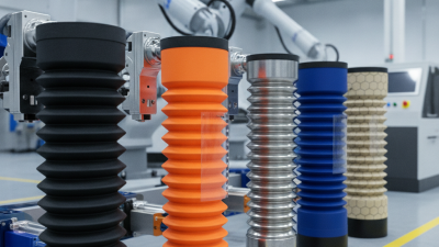
Fixed steel guards generally provide the lowest installed cost but require more space and installation time. Polycarbonate enclosures improve visibility, while telescopic bellows are suitable for moving sections but usually require higher maintenance and validation costs. Actual costs vary with machine size, access doors, interlocks, local labor rates, and required safety testing.