What Is a Tube Bending Machine and How Does It Work?
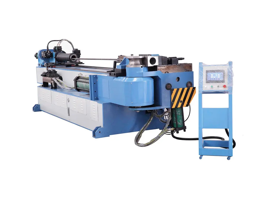
A Tube Bending Machine forms straight metal tubing into accurate curves for frames, exhaust systems, heat exchangers, railings, and industrial structures. It does not simply push a tube around a corner. The machine controls force, support, speed, and rotation while the tube moves through carefully shaped tooling. The result should match the required radius without crushing the section.
“Good tube bending is controlled deformation, not brute force,” explains Peter Van de Laar, a tube-forming engineer frequently associated with practical bending technology. His point is important. A machine must manage several physical effects at once. The outside wall stretches. The inside wall compresses. The cross-section may become oval. Springback can also change the final angle after pressure disappears.
A typical Tube Bending Machine uses a clamp die, bend die, pressure die, and sometimes a mandrel. The mandrel supports the tube from inside. This support helps reduce wrinkles and flattening, especially during tight-radius bends. The operator enters the tube diameter, wall thickness, bend radius, and bend angle. CNC controls then coordinate feeding, rotation, and bending movement.
Small errors matter. A slight setup mistake can leave visible marks or inconsistent angles. That assumption can fail.
Material hardness, lubrication, tooling wear, and tube quality all influence the result. Experienced technicians inspect the first piece, measure the bend, and adjust the program when necessary. No machine removes judgment completely. Reliable production comes from combining sound engineering, suitable tooling, careful measurement, and honest review of each imperfect bend.
What Is a Tube Bending Machine and How Does It Work?
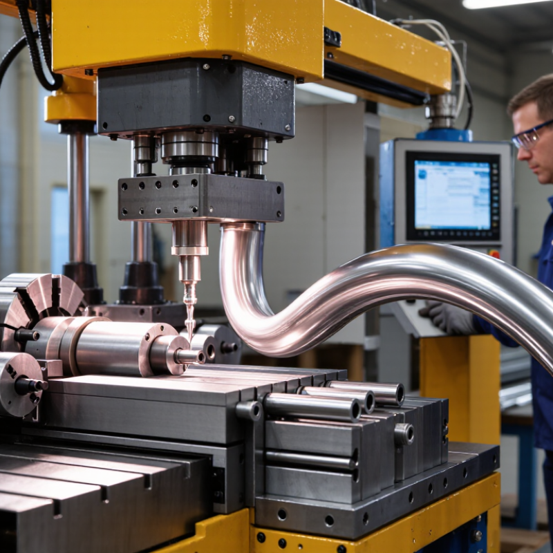
A tube bending machine reshapes hollow metal sections without cutting them. It applies controlled force around a selected radius. The main structure includes a rigid frame, electric or hydraulic drive, tube clamp, bending die, pressure die, and control system. Many machines also use a mandrel inside the tube. This support reduces flattening and prevents wrinkles on thin-wall sections.
The bending die determines the tube’s centerline radius. The clamp holds the tube firmly during rotation. A pressure die supports the outside wall and controls material flow. A wiper die may protect the inside radius from visible ripples. Sensors monitor position, force, and rotation.
These details matter. The International Federation of Robotics reported 541,302 industrial robots installed worldwide in 2023, showing how automation is entering precise manufacturing tasks. Tube bending systems increasingly use similar feedback principles.
During operation, an operator enters tube diameter, wall thickness, bend angle, and radius. The machine clamps the tube, rotates the die, and advances the material through the tooling. The mandrel position must match the material and bend geometry. Otherwise, the tube can collapse or spring back.
The 2024 World Machine Tool Survey reported continued investment in automated production equipment, but automation does not remove setup risk. Tool wear, lubrication, and inconsistent tube quality still affect accuracy. A practical weakness remains: one machine rarely handles every alloy and geometry equally well. Trial bends are still necessary, even in highly controlled workshops.
What Is a Tube Bending Machine and How Does It Work?
A tube bending machine shapes hollow metal sections without cutting them into separate pieces. It applies controlled force around a selected radius. The tube passes through dies that support, clamp, and guide its movement. In rotary draw bending, a clamp die holds the tube against a rotating form die. A pressure die pushes steadily as the tube wraps around the tooling.
Some tubes also need an internal mandrel. This support reduces wrinkles, collapse, and excessive flattening on tight bends. A wiper die can smooth the inside edge near the bend. Operators select tooling according to the tube diameter, wall thickness, material, and required radius. Steel, stainless steel, aluminium, and other alloys respond differently under pressure.
The machine must account for springback, which makes the tube slightly return toward its original shape. Operators often bend beyond the target angle after testing sample pieces. That adjustment is practical, but not always predictable. Small differences in hardness can change the final result. I have seen a visually clean bend fail dimensional checks because its ovality was too high. Measuring the outside diameter and bend angle after forming remains essential. Lubrication, accurate alignment, and steady feeding also protect the surface from scratches and reduce inconsistent wall thinning.
Tube bending machines shape hollow metal sections by applying controlled force around a die. The chart shows the calculated bend allowance for a 25.4 mm outside-diameter tube with a 1.5 mm wall thickness, a 50.8 mm centerline radius, and a neutral-axis factor of 0.33.
Bend allowance increases with the bend angle because the tube travels farther along its neutral axis. The values are calculated using: BA = angle × π/180 × (centerline radius + K × wall thickness).
A tube bending machine forms straight metal tubes into precise curves without cutting the material. The operator first checks the tube’s outside diameter, wall thickness, material grade, and required bend radius. These details determine the correct tooling and machine settings. A small mismatch can create wrinkles, flattening, or cracks.
The tube is then positioned against the mandrel, clamp, pressure die, and forming die. The clamp holds the tube firmly. The mandrel supports the inner wall during tight bends. The forming die controls the curve as the tube rotates or moves forward. Lubrication reduces friction and limits surface damage. After bending, technicians measure the angle, radius, ovality, and wall thinning.
The process needs careful inspection. ASTM E290 bending guidance is often used when evaluating metallic material ductility. According to the International Energy Agency’s Energy Technology Perspectives 2024, industry uses nearly 40% of global final energy, so efficient machine setup matters. Unnecessary trial bends waste material and power. That assumption deserves doubt. Faster is not always better.
The International Federation of Robotics reported more than four million industrial robots operating worldwide in 2023. Automation can improve repeatability, but sensors still need calibration. Skilled operators should review the first formed tube under real lighting, not only trust digital settings. A clean bend is measurable. It is not merely attractive.
A tube bending machine shapes hollow metal sections without cutting them into separate pieces. It applies controlled force around a die, producing accurate curves for different designs. The machine must manage wall thinning, wrinkling, and springback during forming. Small errors can weaken a finished tube. Careful setup matters.
Rotary draw bending is common for exhaust pipes, handrails, frames, and fluid lines. It uses a clamp, pressure die, and forming die to create tight, repeatable bends. Roll bending suits large-radius curves in construction frames and architectural structures. Press bending is simpler and often handles thicker tubes for supports or basic fabrication. Compression bending works well for moderate curves and lower-volume production. CNC tube benders add programmable control for complex parts and repeated batches.
Each type has practical limits. A rotary draw machine offers excellent accuracy, but its tooling can cost more. Roll bending reduces sharp marks, yet it needs more space for long workpieces. CNC equipment improves consistency, although poor programming still creates waste. Operators should check tube diameter, material strength, bend radius, and required surface quality before choosing a machine. Trial bends and dimensional inspection remain valuable, even with advanced controls. No method is perfect. Sometimes, a slower setup produces the more reliable part.
A tube bending machine forms round or shaped tubing around a die, often using rotary draw, roll, or compression bending. Its accuracy depends on more than machine power. Die clearance, tube material, wall thickness, bend radius, and clamping pressure all interact. A small mismatch can leave a visible flat spot near the bend.
Springback is a major concern. High-strength alloys usually recover more after forming, so the programmed angle may need compensation. Wall thinning and ovality also affect strength and appearance. The 2023 World Manufacturing Forum report highlights process consistency and real-time quality control as major manufacturing priorities. Similarly, ASTM E8 testing data shows that material strength changes can significantly influence forming behavior. These references do not replace trial bends, however. Shop-floor results can disagree with a material certificate.
Tips: Measure the tube before bending. Check outside diameter, wall thickness, and hardness at several points. Use a calibrated angle gauge after every setup change. Record pressure, speed, and springback. A 2024 NIST metrology report stresses traceable measurement for reliable dimensional decisions. Keep that principle practical: a clean gauge and steady operator often outperform complicated assumptions. Do not ignore lubrication or worn tooling. They can create scoring, slip, and inconsistent radii. Perfect repeatability is difficult, especially with thin-wall tubing. That limitation deserves honest review.
| Data Dimension | Typical Data or Range | How It Affects the Bending Process | Recommended Control | Common Quality Indicator |
|---|---|---|---|---|
| Tube Material | Carbon steel, stainless steel, aluminum, copper, and alloys | Yield strength, ductility, work hardening, and friction behavior determine the required bending force and the amount of springback. | Use material certificates, confirm the grade, and establish a validated bend allowance for each material condition. | Consistent bend angle, limited surface cracking, and repeatable part dimensions. |
| Outside Diameter | Common production sizes: approximately 6–150 mm | Larger diameters generally require greater machine capacity, larger tooling, and higher clamping force. | Match the pressure die, clamp die, wiper die, and mandrel to the actual tube diameter. | No tube slippage, excessive flattening, or tool marks. |
| Wall Thickness | Specified as a tube wall dimension or wall-to-diameter ratio | Thin-wall tubes are more susceptible to wrinkling, ovalization, and local collapse during bending. | Use a correctly sized mandrel and wiper die; reduce the bend severity or use a larger radius when necessary. | Wall thinning and thickening remain within the design limit, with no visible wrinkles. |
| Centerline Radius | Often expressed as a multiple of outside diameter, such as 1.5D, 2D, or 3D | A smaller radius creates higher tensile and compressive strain and increases the risk of cracking, wrinkling, and distortion. | Select tooling designed for the required radius and verify that the material can withstand the calculated strain. | Required radius is maintained without cracking or unacceptable cross-section distortion. |
| Bend Angle | Typical programmed range: 0°–180° per bend | Springback changes the final angle after the tube is released, especially with high-strength materials and tight radii. | Use machine compensation, test bends, and angle verification after unloading. | Measured angle matches the drawing tolerance after the part has relaxed. |
| Mandrel and Wiper Die | Mandrel support may be fixed, flexible, or ball-type; wiper dies support the inside of tight bends | Internal support controls flattening and wrinkling, particularly in thin-wall tubes and small-radius bends. | Set mandrel position, lubrication, and wiper-die alignment according to the tube size and bend radius. | Round or controlled cross-section, smooth intrados, and minimal wrinkling. |
| Tooling Alignment | Clamp die, pressure die, bend die, mandrel, and tube centerline must be coaxial | Misalignment can cause twist, uneven wall deformation, dimensional drift, and premature tool wear. | Check die seating, centerline height, clamp pressure, and machine calibration before production. | Stable bend location, low twist, and consistent dimensions from part to part. |
| Lubrication | Applied according to tube material, tooling, temperature, and lubricant specification | Insufficient lubrication increases friction, surface scoring, required force, and the possibility of material galling. | Apply an even film to the mandrel and contact surfaces; remove residue when cleanliness is required. | Low scratch rate, smooth movement, and stable forming force. |
| Bending Speed | Set by machine capacity, material behavior, tooling, and bend complexity | Excessive speed can increase vibration, heat, slipping, and inconsistent deformation; very low speed may reduce productivity. | Use a controlled speed profile and qualify the setting with trial parts and dimensional checks. | Repeatable angle and position with no chatter marks or sudden deformation. |
| Springback Compensation | Usually established through trial bends or a validated machine model | Elastic recovery causes the tube to open or change position after forming, with the amount varying by material and geometry. | Record measured compensation values by material, diameter, wall thickness, and radius. | Final unloaded geometry remains within the specified angle and location tolerances. |
| Cross-Section Ovalization | Measured as the change from the original circular profile | Bending compresses the inside of the tube and stretches the outside, changing the cross-section from round to oval. | Use adequate mandrel support, correct tooling clearance, and a suitable bend radius. | Ovality remains below the maximum value permitted by the drawing or applicable standard. |
| Inspection Method | Calipers, angle gauges, radius gauges, coordinate measurement, or 3D scanning | The inspection method and datum strategy affect how accurately bend angle, position, radius, and twist are evaluated. | Define datums, sampling frequency, and measurement uncertainty before production approval. | Documented results show compliance with dimensional and visual requirements. |